Pbm27a210mvr Diagram Full !!better!! Link
Version: 2.2.15 (2020-12-05)
Windows 32-bit or 64-bit supported
Version: 2.2.15 (2020-12-05)
Windows 32-bit or 64-bit supported
Search Google/Bing for:
: Includes OTP memory that stores factory calibration data, allowing for temperature-compensated and pressure-calibrated outputs right out of the box.
: A circuit diagram mapping the flow of current from the power source (battery or plug) through the control switch to the motor or heating element.
Identification of I2C and SPI interface pins for microcontroller communication.
Stores custom parameters and operational limits.
The can be divided into four functional quadrants. We will describe each as you would see them on the actual schematic.
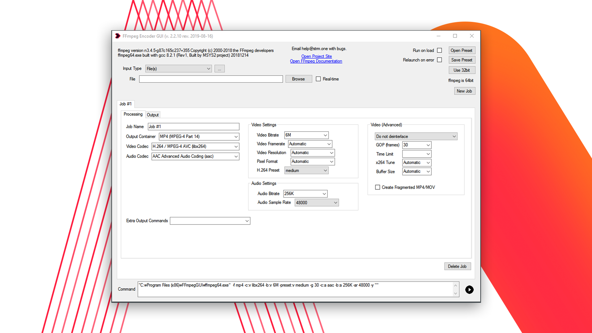
FFmpegGUI currently supports File, DirectShow, Blackmagic Decklink, NewTek NDI or URL inputs.
Drag and drop your file(s) from your system to be processed quickly.
Prompting to rename any input file(s) with non-ASCII filenames to be compatible with command-line processor. pbm27a210mvr diagram full
You can easily export your clip(s) to a file, NewTek NDI destination, RTMP server or any other custom output supported by FFmpeg.
The included FFmpeg is built with hardware encoding support for NVENC. GUI support is experimental at this time, feedback is welcome. Search Google/Bing for: : Includes OTP memory that
32-bit and 64-bit Windows binaries of FFmpeg included. Current binaries are based on version 3.4.5.
Save your encoding settings as file to be recalled later. Settings are formatted as an XML document. pbm27a210mvr diagram full
GUI project is developed by ffmpeg fans and distributed for any usage. Non-free codecs in the included FFmpeg build may have further restrictions.
Search Google/Bing for:
: Includes OTP memory that stores factory calibration data, allowing for temperature-compensated and pressure-calibrated outputs right out of the box.
: A circuit diagram mapping the flow of current from the power source (battery or plug) through the control switch to the motor or heating element.
Identification of I2C and SPI interface pins for microcontroller communication.
Stores custom parameters and operational limits.
The can be divided into four functional quadrants. We will describe each as you would see them on the actual schematic.